Hace ya tiempo que tenia ganas de testear estos módulos, no había tenido la oportunidad hasta un par de días. debo mencionar que no soy el autor de la librería y tampoco del demo que les muestro aquí, lo único que realice fue las adecuaciones para trabajar con el PIC18F25K22 y PIC18F46K22, como transmisor y receptor respectivamente, puedes revisar el código original aquí (actualmente ya no esta disponible el repositorio original).
Circuitos:
En la fuente original no se muestra esquemático alguno, pero checando el código, un poco de teoría y las hojas de datos se puede montar el circuito sin ningún problema, otra modificación realizada es el oscilador, la versión original usa un cristal externo de 16MHz, yo he usado el oscilador interno a la misma frecuencia.
A continuación muestro el esquemático que use para el transmisor, dedo comentar que modifique el pin del LED debido a que use el PIC18F25K22 y este no cuenta con un PORTD (en donde estaba originalmente), en cuanto a la alimentación de ambos circuitos es a 3.3 volts.
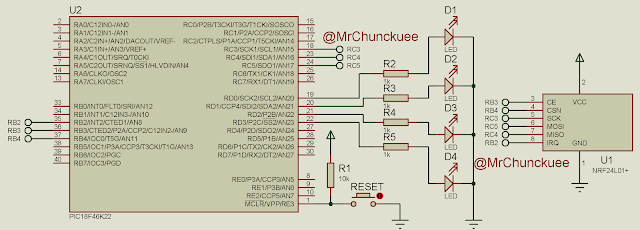
Como ya mencione he usado el PIC18F46K22 para el receptor, y el circuito usado es el siguiente:
Como el circuito lo monte sobre la protoboard y es notable que los nRF no los podía colocar directamente, realice unas pequeñas adecuaciones con tiras de pines y headers dobles, a continuación las fotos.
Listo los módulos se pueden colocar sin conflicto alguno.
Para el transmisor quedo de la siguiente forma:
El archivo main.c para el transmisor es el siguiente:
This file contains hidden or bidirectional Unicode text that may be interpreted or compiled differently than what appears below. To review, open the file in an editor that reveals hidden Unicode characters.
Learn more about bidirectional Unicode characters
/* | |
* 2013 Elia Ritterbusch | |
* http://eliaselectronics.com | |
* | |
* This work is licensed under the Creative Commons Attribution 3.0 Unported License. | |
* To view a copy of this license, visit http://creativecommons.org/licenses/by/3.0/ | |
*/ | |
/******************************************************************************* | |
* | |
* XC8_006: Probando modulos nRF24L01+ | |
* | |
******************************************************************************* | |
* FileName: main.c | |
* Processor: PIC18F25K22 | |
* Complier: XC8 v1.30 | |
* Author: Pedro Sánchez (MrChunckuee) | |
* Blog: http://mrchunckuee.blogspot.com/ | |
* Email: mrchunckuee.psr@gmail.com | |
* Description: Probando libreria para los modulos nRF24L01+ | |
******************************************************************************* | |
* Rev. Date Comment | |
* v1.01 06/04/2017 Modificacion para usar el PIC18F25K22 | |
******************************************************************************/ | |
#define _XTAL_FREQ 16000000UL | |
#include <xc.h> | |
#include <stdlib.h> | |
#include "spi.h" | |
#include "nRF24L01.h" | |
#include "wl_module.h" | |
// PIC18F25K22 Configuration Bit Settings | |
// 'C' source line config statements | |
// CONFIG1H | |
#pragma config FOSC = INTIO67 // Oscillator Selection bits (Internal oscillator block) | |
#pragma config PLLCFG = OFF // 4X PLL Enable (Oscillator used directly) | |
#pragma config PRICLKEN = OFF // Primary clock enable bit (Primary clock can be disabled by software) | |
#pragma config FCMEN = ON // Fail-Safe Clock Monitor Enable bit (Fail-Safe Clock Monitor enabled) | |
#pragma config IESO = OFF // Internal/External Oscillator Switchover bit (Oscillator Switchover mode disabled) | |
// CONFIG2L | |
#pragma config PWRTEN = ON // Power-up Timer Enable bit (Power up timer enabled) | |
#pragma config BOREN = SBORDIS // Brown-out Reset Enable bits (Brown-out Reset enabled in hardware only (SBOREN is disabled)) | |
#pragma config BORV = 190 // Brown Out Reset Voltage bits (VBOR set to 1.90 V nominal) | |
// CONFIG2H | |
#pragma config WDTEN = OFF // Watchdog Timer Enable bits (Watch dog timer is always disabled. SWDTEN has no effect.) | |
#pragma config WDTPS = 32768 // Watchdog Timer Postscale Select bits (1:32768) | |
// CONFIG3H | |
#pragma config CCP2MX = PORTC1 // CCP2 MUX bit (CCP2 input/output is multiplexed with RC1) | |
#pragma config PBADEN = ON // PORTB A/D Enable bit (PORTB<5:0> pins are configured as analog input channels on Reset) | |
#pragma config CCP3MX = PORTB5 // P3A/CCP3 Mux bit (P3A/CCP3 input/output is multiplexed with RB5) | |
#pragma config HFOFST = ON // HFINTOSC Fast Start-up (HFINTOSC output and ready status are not delayed by the oscillator stable status) | |
#pragma config T3CMX = PORTC0 // Timer3 Clock input mux bit (T3CKI is on RC0) | |
#pragma config P2BMX = PORTB5 // ECCP2 B output mux bit (P2B is on RB5) | |
#pragma config MCLRE = EXTMCLR // MCLR Pin Enable bit (MCLR pin enabled, RE3 input pin disabled) | |
// CONFIG4L | |
#pragma config STVREN = ON // Stack Full/Underflow Reset Enable bit (Stack full/underflow will cause Reset) | |
#pragma config LVP = ON // Single-Supply ICSP Enable bit (Single-Supply ICSP enabled if MCLRE is also 1) | |
#pragma config XINST = OFF // Extended Instruction Set Enable bit (Instruction set extension and Indexed Addressing mode disabled (Legacy mode)) | |
// CONFIG5L | |
#pragma config CP0 = OFF // Code Protection Block 0 (Block 0 (000800-001FFFh) not code-protected) | |
#pragma config CP1 = OFF // Code Protection Block 1 (Block 1 (002000-003FFFh) not code-protected) | |
#pragma config CP2 = OFF // Code Protection Block 2 (Block 2 (004000-005FFFh) not code-protected) | |
#pragma config CP3 = OFF // Code Protection Block 3 (Block 3 (006000-007FFFh) not code-protected) | |
// CONFIG5H | |
#pragma config CPB = OFF // Boot Block Code Protection bit (Boot block (000000-0007FFh) not code-protected) | |
#pragma config CPD = OFF // Data EEPROM Code Protection bit (Data EEPROM not code-protected) | |
// CONFIG6L | |
#pragma config WRT0 = OFF // Write Protection Block 0 (Block 0 (000800-001FFFh) not write-protected) | |
#pragma config WRT1 = OFF // Write Protection Block 1 (Block 1 (002000-003FFFh) not write-protected) | |
#pragma config WRT2 = OFF // Write Protection Block 2 (Block 2 (004000-005FFFh) not write-protected) | |
#pragma config WRT3 = OFF // Write Protection Block 3 (Block 3 (006000-007FFFh) not write-protected) | |
// CONFIG6H | |
#pragma config WRTC = OFF // Configuration Register Write Protection bit (Configuration registers (300000-3000FFh) not write-protected) | |
#pragma config WRTB = OFF // Boot Block Write Protection bit (Boot Block (000000-0007FFh) not write-protected) | |
#pragma config WRTD = OFF // Data EEPROM Write Protection bit (Data EEPROM not write-protected) | |
// CONFIG7L | |
#pragma config EBTR0 = OFF // Table Read Protection Block 0 (Block 0 (000800-001FFFh) not protected from table reads executed in other blocks) | |
#pragma config EBTR1 = OFF // Table Read Protection Block 1 (Block 1 (002000-003FFFh) not protected from table reads executed in other blocks) | |
#pragma config EBTR2 = OFF // Table Read Protection Block 2 (Block 2 (004000-005FFFh) not protected from table reads executed in other blocks) | |
#pragma config EBTR3 = OFF // Table Read Protection Block 3 (Block 3 (006000-007FFFh) not protected from table reads executed in other blocks) | |
// CONFIG7H | |
#pragma config EBTRB = OFF // Boot Block Table Read Protection bit (Boot Block (000000-0007FFh) not protected from table reads executed in other blocks) | |
// #pragma config statements should precede project file includes. | |
// Use project enums instead of #define for ON and OFF. | |
#define MAX_STRLEN 14 | |
char received_string[MAX_STRLEN+1]; | |
void _delay_10ms(int length){ | |
while(length){ | |
__delay_ms(10); | |
length--; | |
} | |
} | |
int main(void){ | |
unsigned char payload[wl_module_PAYLOAD]; //Array for Payload | |
unsigned char maincounter =0; | |
unsigned char k; | |
OSCCONbits.IRCF = 0b111; //Internal Fosc = 16MHz | |
// status pin to indicate when master | |
// sends a message only for debugging | |
TRISCbits.TRISC7 = 0; | |
LATCbits.LATC7 = 1; | |
wl_module_init(); //initialise nRF24L01+ Module | |
_delay_10ms(5); //wait for nRF24L01+ Module | |
INTCONbits.PEIE = 1; // peripheral interrupts enabled | |
INTCONbits.GIE = 1; // global interrupt enable | |
wl_module_tx_config(wl_module_TX_NR_0); //Config Module | |
while(1){ | |
LATCbits.LATC7 = 0; // turn indicator LED on | |
for (k=0; k<=wl_module_PAYLOAD-1; k++){ | |
payload[k] = k; | |
} | |
payload[0] = maincounter; | |
payload[1] = maincounter+1; | |
wl_module_send(payload,wl_module_PAYLOAD); | |
maincounter++; | |
if (maincounter > 0x0F){ | |
maincounter = 0; | |
} | |
_delay_10ms(50); | |
LATCbits.LATC7 = 1; // turn indicator LED off | |
_delay_10ms(50); | |
} | |
return 0; | |
} | |
void interrupt ISR(void){ | |
// external interrupt IRQ pin of NRF24L01 | |
if( INTCON3bits.INT2IF ){ | |
unsigned char status; | |
// Read wl_module status | |
wl_module_CSN_lo; // Pull down chip select | |
status = spi_fast_shift(NOOP); // Read status register | |
wl_module_CSN_hi; // Pull up chip select | |
if (status & (1<<TX_DS)){ // IRQ: Package has been sent | |
wl_module_config_register(STATUS, (1<<TX_DS)); //Clear Interrupt Bit | |
PTX=0; | |
} | |
if (status & (1<<MAX_RT)){ // IRQ: Package has not been sent, send again | |
wl_module_config_register(STATUS, (1<<MAX_RT)); // Clear Interrupt Bit | |
wl_module_CE_hi; // Start transmission | |
__delay_us(10); | |
wl_module_CE_lo; | |
} | |
if (status & (1<<TX_FULL)){ //TX_FIFO Full <-- this is not an IRQ | |
wl_module_CSN_lo; // Pull down chip select | |
spi_fast_shift(FLUSH_TX); // Flush TX-FIFO | |
wl_module_CSN_hi; // Pull up chip select | |
} | |
// reset INT2 flag | |
INTCON3bits.INT2IF = 0; | |
} | |
} |
El archivo main.c para el receptor es el siguiente:
This file contains hidden or bidirectional Unicode text that may be interpreted or compiled differently than what appears below. To review, open the file in an editor that reveals hidden Unicode characters.
Learn more about bidirectional Unicode characters
/* | |
* 2013 Elia Ritterbusch | |
* http://eliaselectronics.com | |
* | |
* This work is licensed under the Creative Commons Attribution 3.0 Unported License. | |
* To view a copy of this license, visit http://creativecommons.org/licenses/by/3.0/ | |
*/ | |
/******************************************************************************* | |
* | |
* XC8_006: Probando modulos nRF24L01+ | |
* | |
******************************************************************************* | |
* FileName: main.c | |
* Processor: PIC18F46K22 | |
* Complier: XC8 v1.30 | |
* Author: Pedro Sánchez (MrChunckuee) | |
* Blog: http://mrchunckuee.blogspot.com/ | |
* Email: mrchunckuee.psr@gmail.com | |
* Description: Probando libreria para los modulos nRF24L01+ | |
******************************************************************************* | |
* Rev. Date Comment | |
* v1.01 06/04/2017 Modificacion para usar el PIC18F46K22 | |
******************************************************************************/ | |
#define _XTAL_FREQ 16000000UL | |
#include <xc.h> | |
#include <stdlib.h> | |
#include "spi.h" | |
#include "nRF24L01.h" | |
#include "wl_module.h" | |
// PIC18F46K22 Configuration Bit Settings | |
// 'C' source line config statements | |
// CONFIG1H | |
#pragma config FOSC = INTIO67 // Oscillator Selection bits (Internal oscillator block) | |
#pragma config PLLCFG = OFF // 4X PLL Enable (Oscillator used directly) | |
#pragma config PRICLKEN = OFF // Primary clock enable bit (Primary clock can be disabled by software) | |
#pragma config FCMEN = ON // Fail-Safe Clock Monitor Enable bit (Fail-Safe Clock Monitor enabled) | |
#pragma config IESO = OFF // Internal/External Oscillator Switchover bit (Oscillator Switchover mode disabled) | |
// CONFIG2L | |
#pragma config PWRTEN = ON // Power-up Timer Enable bit (Power up timer enabled) | |
#pragma config BOREN = SBORDIS // Brown-out Reset Enable bits (Brown-out Reset enabled in hardware only (SBOREN is disabled)) | |
#pragma config BORV = 190 // Brown Out Reset Voltage bits (VBOR set to 1.90 V nominal) | |
// CONFIG2H | |
#pragma config WDTEN = OFF // Watchdog Timer Enable bits (Watch dog timer is always disabled. SWDTEN has no effect.) | |
#pragma config WDTPS = 32768 // Watchdog Timer Postscale Select bits (1:32768) | |
// CONFIG3H | |
#pragma config CCP2MX = PORTC1 // CCP2 MUX bit (CCP2 input/output is multiplexed with RC1) | |
#pragma config PBADEN = ON // PORTB A/D Enable bit (PORTB<5:0> pins are configured as analog input channels on Reset) | |
#pragma config CCP3MX = PORTB5 // P3A/CCP3 Mux bit (P3A/CCP3 input/output is multiplexed with RB5) | |
#pragma config HFOFST = ON // HFINTOSC Fast Start-up (HFINTOSC output and ready status are not delayed by the oscillator stable status) | |
#pragma config T3CMX = PORTC0 // Timer3 Clock input mux bit (T3CKI is on RC0) | |
#pragma config P2BMX = PORTD2 // ECCP2 B output mux bit (P2B is on RD2) | |
#pragma config MCLRE = EXTMCLR // MCLR Pin Enable bit (MCLR pin enabled, RE3 input pin disabled) | |
// CONFIG4L | |
#pragma config STVREN = ON // Stack Full/Underflow Reset Enable bit (Stack full/underflow will cause Reset) | |
#pragma config LVP = ON // Single-Supply ICSP Enable bit (Single-Supply ICSP enabled if MCLRE is also 1) | |
#pragma config XINST = OFF // Extended Instruction Set Enable bit (Instruction set extension and Indexed Addressing mode disabled (Legacy mode)) | |
// CONFIG5L | |
#pragma config CP0 = OFF // Code Protection Block 0 (Block 0 (000800-003FFFh) not code-protected) | |
#pragma config CP1 = OFF // Code Protection Block 1 (Block 1 (004000-007FFFh) not code-protected) | |
#pragma config CP2 = OFF // Code Protection Block 2 (Block 2 (008000-00BFFFh) not code-protected) | |
#pragma config CP3 = OFF // Code Protection Block 3 (Block 3 (00C000-00FFFFh) not code-protected) | |
// CONFIG5H | |
#pragma config CPB = OFF // Boot Block Code Protection bit (Boot block (000000-0007FFh) not code-protected) | |
#pragma config CPD = OFF // Data EEPROM Code Protection bit (Data EEPROM not code-protected) | |
// CONFIG6L | |
#pragma config WRT0 = OFF // Write Protection Block 0 (Block 0 (000800-003FFFh) not write-protected) | |
#pragma config WRT1 = OFF // Write Protection Block 1 (Block 1 (004000-007FFFh) not write-protected) | |
#pragma config WRT2 = OFF // Write Protection Block 2 (Block 2 (008000-00BFFFh) not write-protected) | |
#pragma config WRT3 = OFF // Write Protection Block 3 (Block 3 (00C000-00FFFFh) not write-protected) | |
// CONFIG6H | |
#pragma config WRTC = OFF // Configuration Register Write Protection bit (Configuration registers (300000-3000FFh) not write-protected) | |
#pragma config WRTB = OFF // Boot Block Write Protection bit (Boot Block (000000-0007FFh) not write-protected) | |
#pragma config WRTD = OFF // Data EEPROM Write Protection bit (Data EEPROM not write-protected) | |
// CONFIG7L | |
#pragma config EBTR0 = OFF // Table Read Protection Block 0 (Block 0 (000800-003FFFh) not protected from table reads executed in other blocks) | |
#pragma config EBTR1 = OFF // Table Read Protection Block 1 (Block 1 (004000-007FFFh) not protected from table reads executed in other blocks) | |
#pragma config EBTR2 = OFF // Table Read Protection Block 2 (Block 2 (008000-00BFFFh) not protected from table reads executed in other blocks) | |
#pragma config EBTR3 = OFF // Table Read Protection Block 3 (Block 3 (00C000-00FFFFh) not protected from table reads executed in other blocks) | |
// CONFIG7H | |
#pragma config EBTRB = OFF // Boot Block Table Read Protection bit (Boot Block (000000-0007FFh) not protected from table reads executed in other blocks) | |
// #pragma config statements should precede project file includes. | |
// Use project enums instead of #define for ON and OFF. | |
#define MAX_STRLEN 14 | |
char received_string[MAX_STRLEN+1]; | |
void _delay_10ms(int length){ | |
while(length){ | |
__delay_ms(10); | |
length--; | |
} | |
} | |
int main(void){ | |
unsigned char payload[wl_module_PAYLOAD]; //holds the payload | |
unsigned char nRF_status; //STATUS information of nRF24L01+ | |
unsigned char zaehler = 0; | |
OSCCONbits.IRCF = 0b111; //Internal Fosc = 16MHz | |
wl_module_init(); //Init nRF Module | |
_delay_10ms(5); //wait for Module | |
// configure output port | |
TRISD &= ~(0x0F); | |
LATD |= 0x0F; | |
INTCONbits.PEIE = 1; // peripheral interrupts enabled | |
INTCONbits.GIE = 1; // global interrupt enable | |
wl_module_config(); //config nRF as RX Module, simple Version | |
while(1){ | |
while (!wl_module_data_ready()); //waits for RX_DR Flag in STATUS | |
nRF_status = wl_module_get_data(payload); //reads the incomming Data to Array payload | |
zaehler = payload[0]; | |
LATD |= 0x0F; | |
LATD &= ~(payload[0]); | |
} | |
return 0; | |
} | |
void interrupt ISR(void){ | |
// external interrupt IRQ pin of NRF24L01 | |
if( INTCON3bits.INT2IF ){ | |
unsigned char status; | |
// Read wl_module status | |
wl_module_CSN_lo; // Pull down chip select | |
status = spi_fast_shift(NOOP); // Read status register | |
wl_module_CSN_hi; // Pull up chip select | |
if (status & (1<<TX_DS)){ // IRQ: Package has been sent | |
wl_module_config_register(STATUS, (1<<TX_DS)); //Clear Interrupt Bit | |
PTX=0; | |
} | |
if (status & (1<<MAX_RT)){ // IRQ: Package has not been sent, send again | |
wl_module_config_register(STATUS, (1<<MAX_RT)); // Clear Interrupt Bit | |
wl_module_CE_hi; // Start transmission | |
__delay_us(10); | |
wl_module_CE_lo; | |
} | |
if (status & (1<<TX_FULL)){ //TX_FIFO Full <-- this is not an IRQ | |
wl_module_CSN_lo; // Pull down chip select | |
spi_fast_shift(FLUSH_TX); // Flush TX-FIFO | |
wl_module_CSN_hi; // Pull up chip select | |
} | |
// reset INT2 flag | |
INTCON3bits.INT2IF = 0; | |
} | |
} |
un pequeño video donde muestra los módulos en acción:
Descargas:
Aquí el enlace directo para DESCARGAR los archivos disponibles, también puedes revisar o descargar la información desde mi repositorio en GitHub, si no sabes como descargarlo puedes checar aquí, bueno por el momento es todo si tienes dudas, comentarios, sugerencias, inquietudes, traumas, etc. dejarlas y tratare de responder lo mas pronto posible.
Donaciones:
Si te gusta el contenido o si los recursos te son de utilidad, comparte el enlace en tus redes sociales o sitios donde creas que puede ser de interés y la otra puedes ayudarme con una donación para seguir realizando publicaciones y mejorar el contenido del sitio. También puedes hacer donaciones en especie, ya sea con componentes, tarjetas de desarrollo o herramientas. Ponte en contacto para platicar, o puedes volverte uno de nuestros sponsors.
Pido una retroalimentación avisando cada que un enlace no sirva o tenga errores al momento de abrirlo, así también si una imagen no se ve o no carga, para corregirlo en el menor tiempo posible.
2 Comentarios
Hola.
ResponderEliminarLo primero agradecer tus aportes.
Sabes porque al compilar tu proyecto me salen un monton de warnings de funciones no llamadas y de conversion a datos de tipo mas corto, y en el proyecto original de github no salen siendo practicamente iguales.
Estoy trabajando con mplabx ide ver 2.10 y xc8 v1.34
Gracias
Pues yo estoy usando MPLAB X v3.61 & XC8 v1.42 y tambien me marcan los warnings sobre funciones no llamadas (llegue a casa a compilarlo nuevamente), desconozco el por que el original no los marca, de hecho yo no compile el original directamente cree un proyecto y agregue las librerias. A pesar de eso el demo trabaja bien.
Eliminar